
Custom CAD Templates
AirWorks supports custom CAD layer templates to allow users to receive their orders in their own unique layers (names, line styles, weights, and colors). There are no limits to the number of custom templates that can be added to an account.
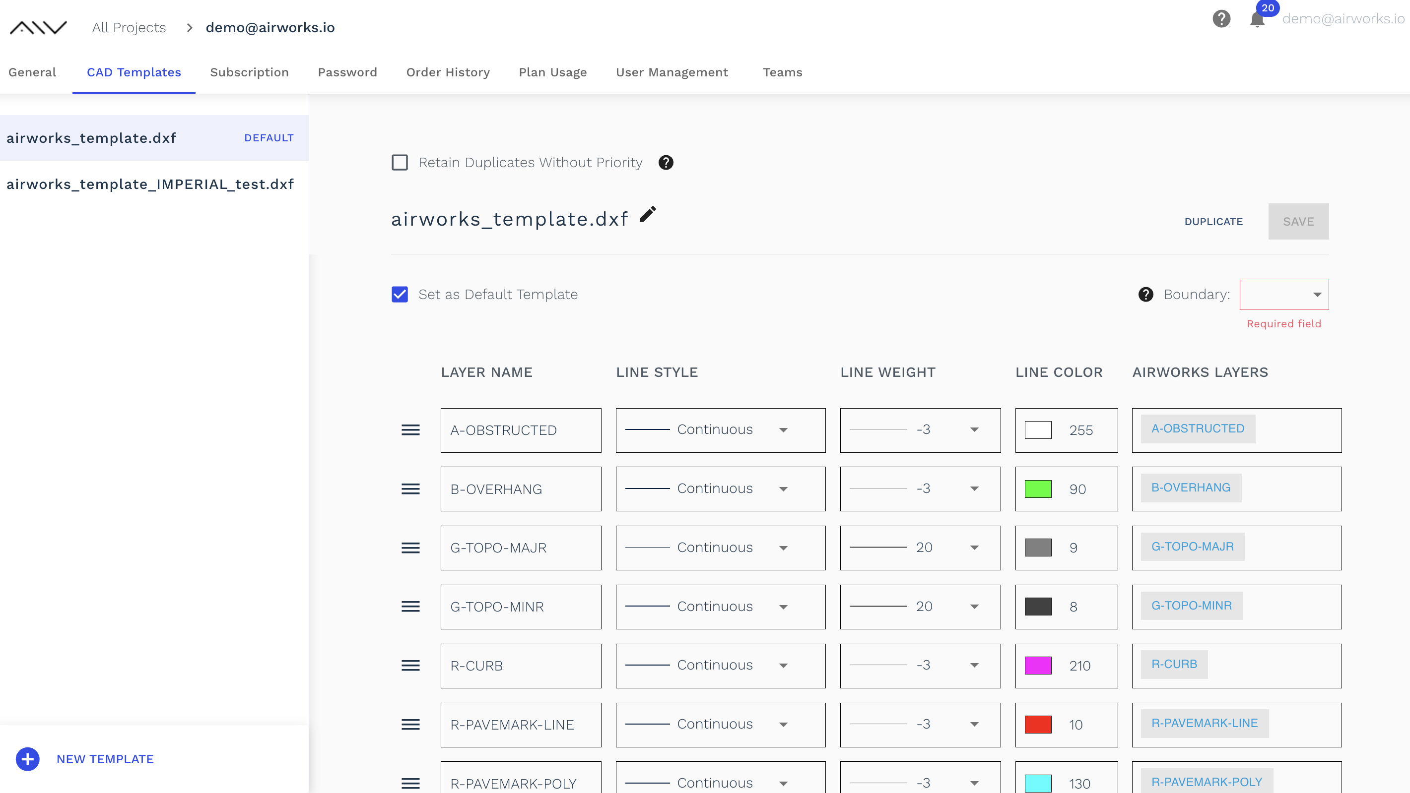
The custom CAD template feature can be found within account settings in the “CAD Templates” tab.
You will see the two AirWorks standard templates list here in the left sidebar.
Creating a new template:
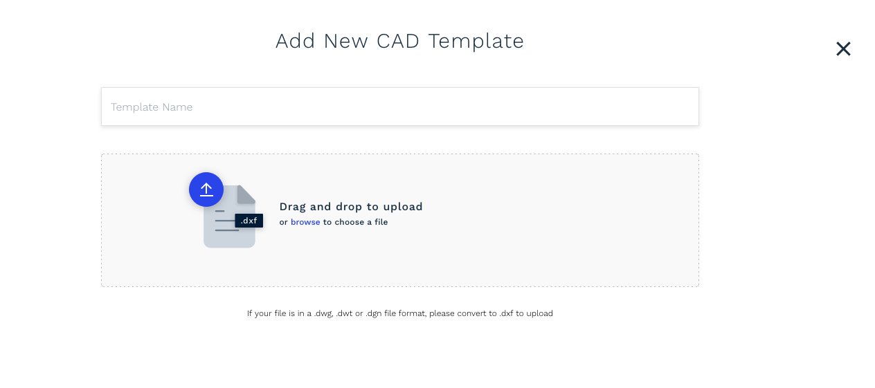
#1: Click on the “NEW TEMPLATE” button at the bottom of the left sidebar.
#2: Name your template and select a .dxf file to upload.
Please only upload .dxf files as templates, other files formats like .dwg should be converted into .dxf prior to uploading.
Once you select the file to upload (or drop it in the upload box) your will see a status bar indicating the file is in the process of uploading.
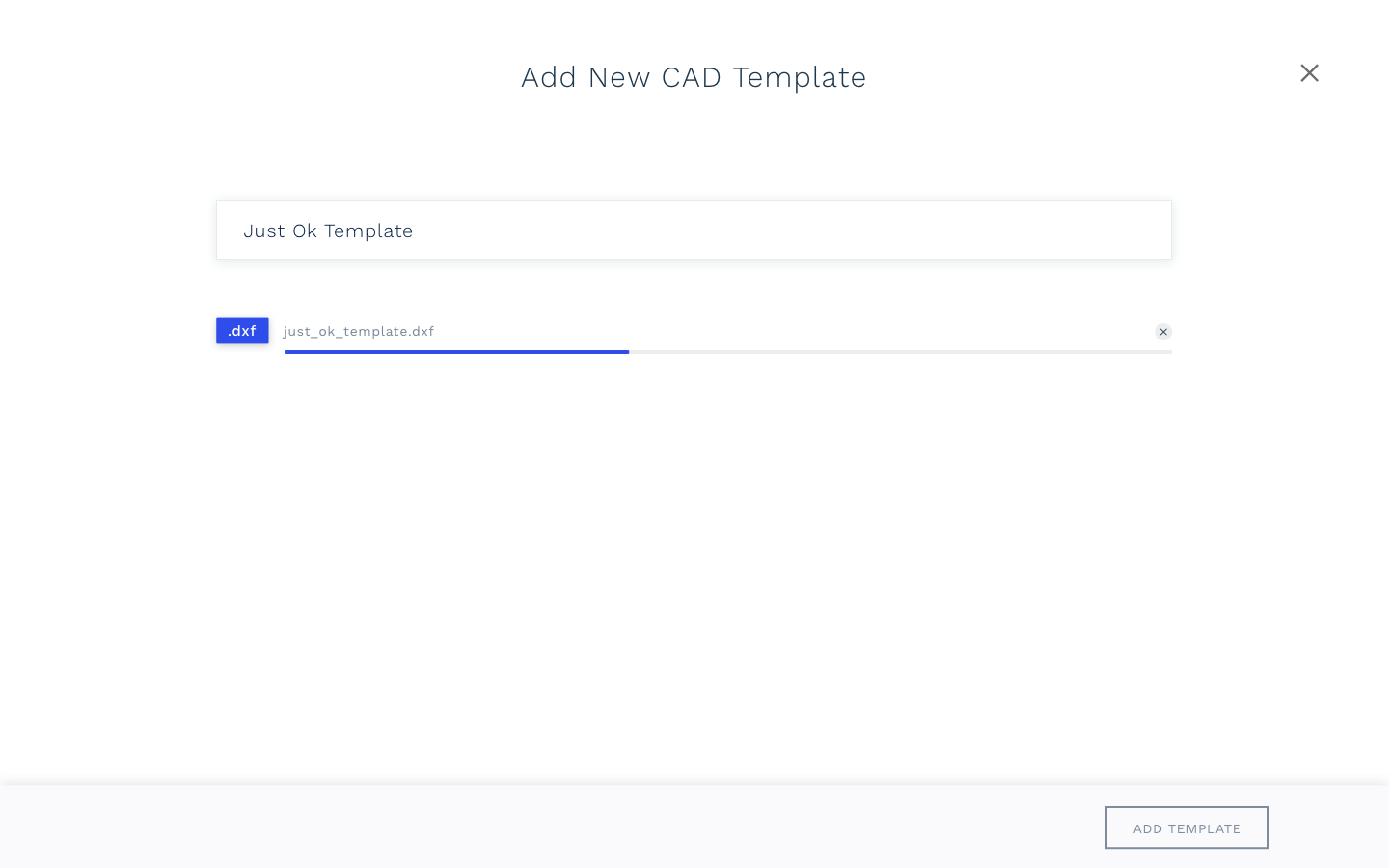
CAD template file upload in progress.
#3: Click on Add Template at the bottom of the page and move on to matching your existing layers to our default layers.
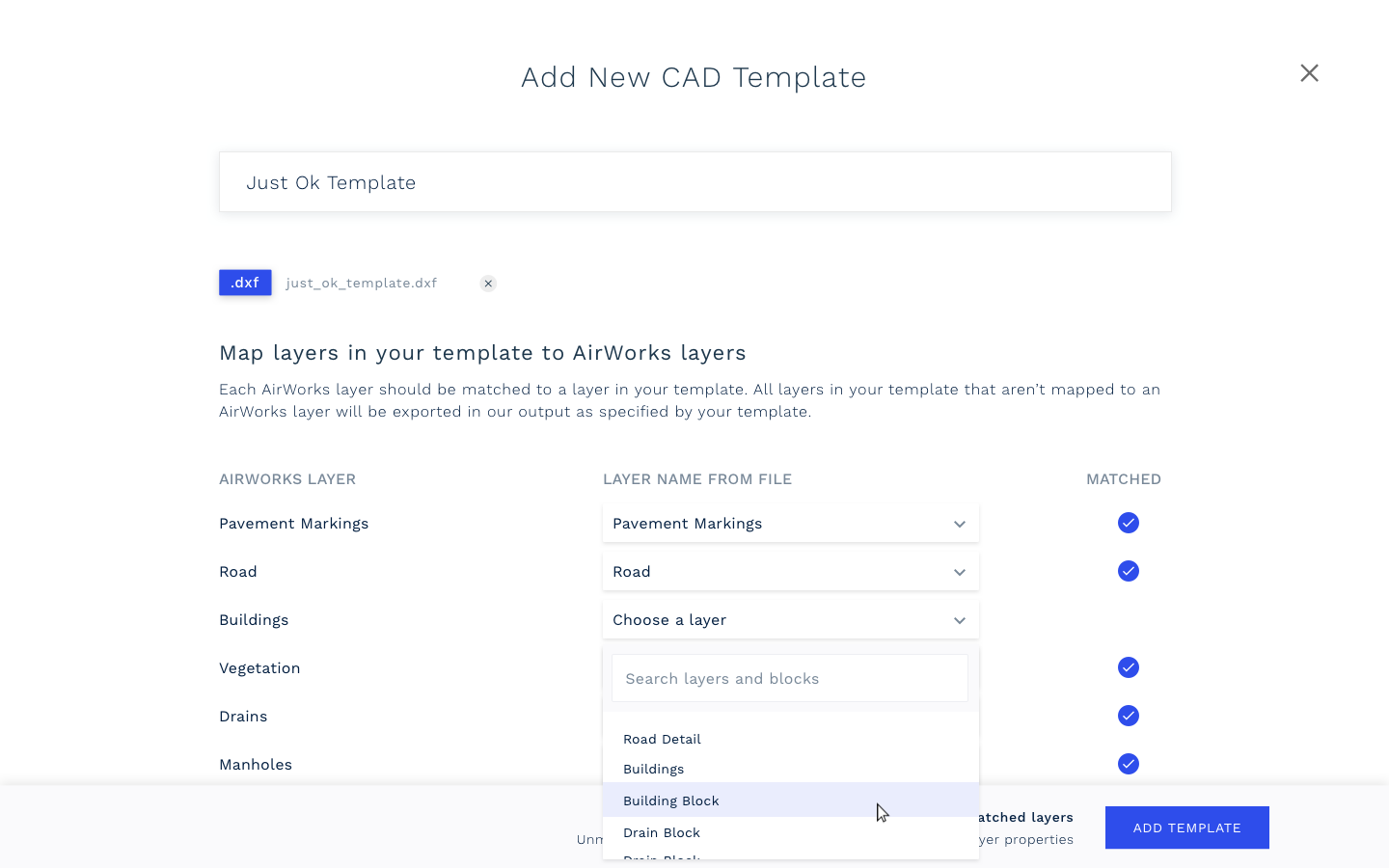
In the next window, the column “AIRWORKS LAYER” shows all of the layers that our software currently identifies and maps. You should go through your list of layers from the file and map them accordingly to the existing AirWorks layers. For example, you may choose to map your layer called “Plumbing” to the AirWorks layer called “Drains”. You can also choose to leave some layers unmatched.
#4: Click on Add Template and move on to selecting the line styles for each layer.
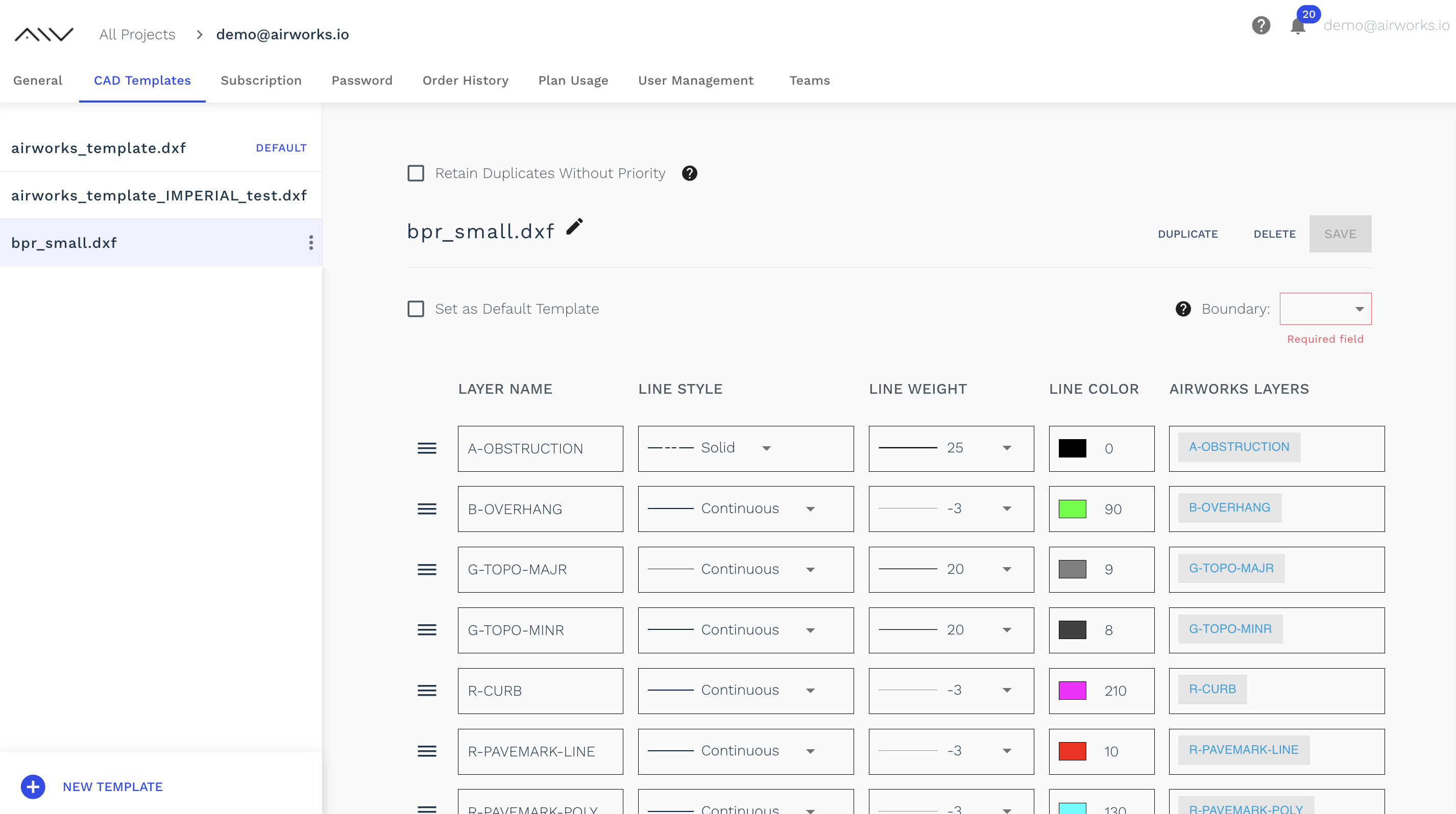
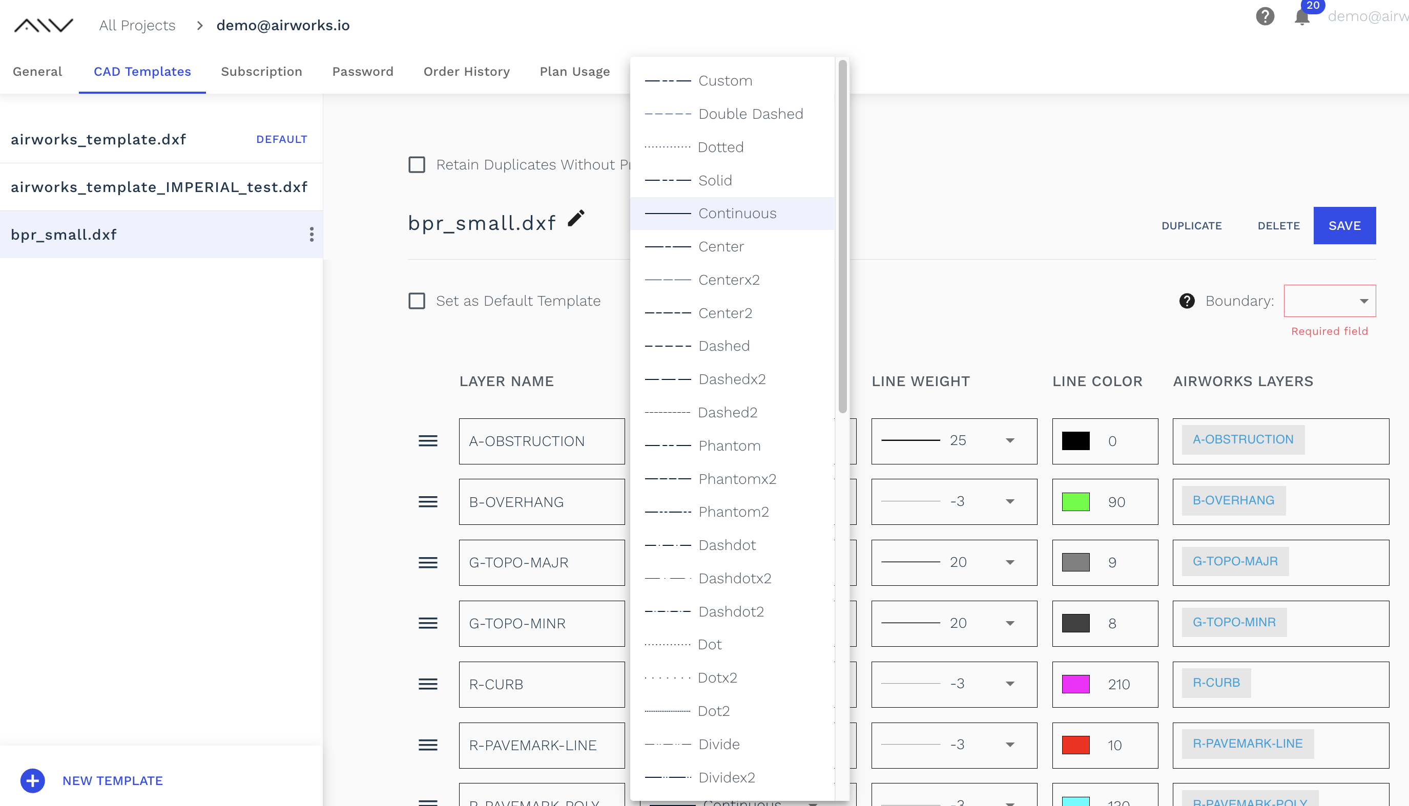
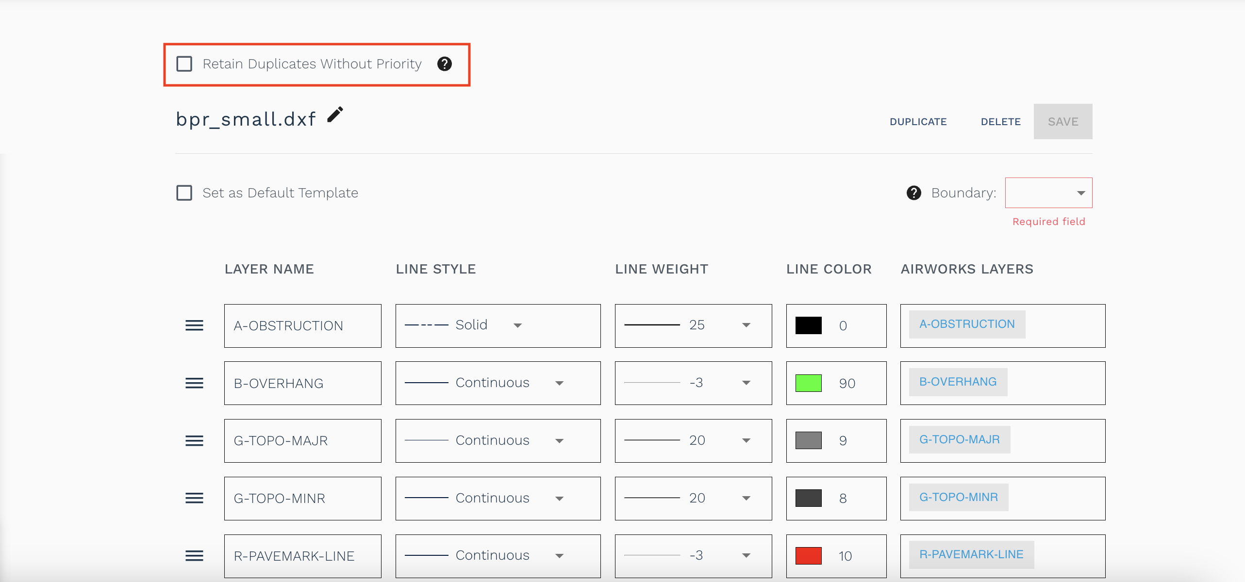
Here you can assign line styles, weights, and colors to each of the layers in your CAD template by selecting your desired option from the dropdown menus, as well as make changes to the AirWorks layers that you have assigned to each of your layers.
#5 To prioritize the different layers you have, simply click on the list order icon of any row and slide up/down as shown below. By assigning higher priority to specific layers, you can control which layers are prioritized when two or more layers intersects or overlaps. This improves visibility and clarity of the output.
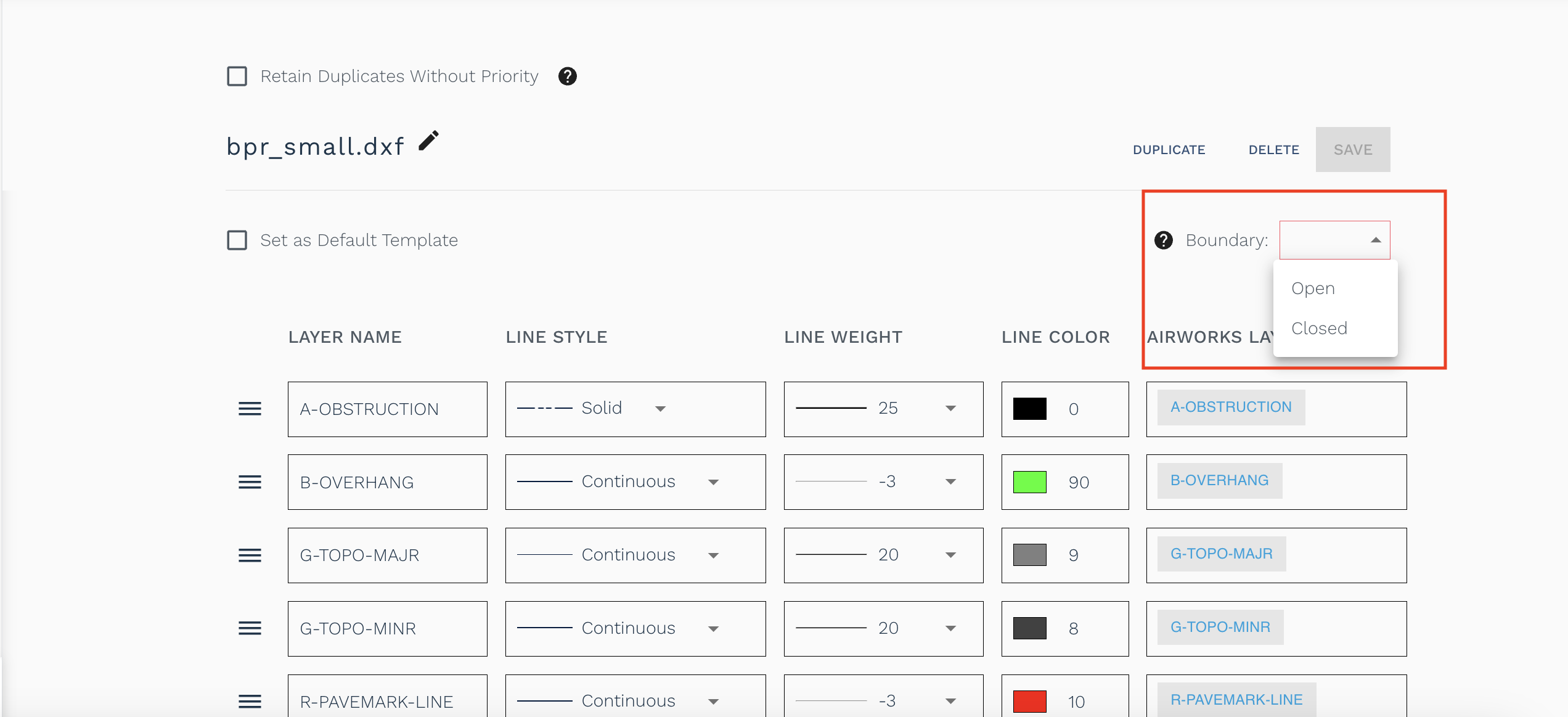
#6 Click on the dropdown next to “Boundary” to choose between open/closed boundaries for your CAD output. This is a required field, that lets users choose whether their outputs should reflect real-world conditions (open boundaries) or whether they intend to run area or perimeter type calculations on features in their dataset by having AirWorks provide closed polygons instead.
#7 The “Retain Duplicates Without Priority” option indicates users don’t have any need for layer prioritization and are happy to receive overlapping linework which reflects real world conditions like a road and curb layer sharing a boundary.
Editing an existing CAD template:
Editing an existing template can be done by simply going to your Account Settings page, in the CAD Templates tab, and selecting which template you want to edit. From here you can change the name of your template, rearrange your mapped AirWorks layers and change your chosen line styles. To see your changes reflected, make sure to click the Save button at the top of the page.